About Sika Greenstreak Split Flange PVC Waterstop
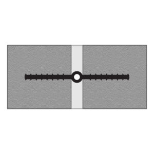
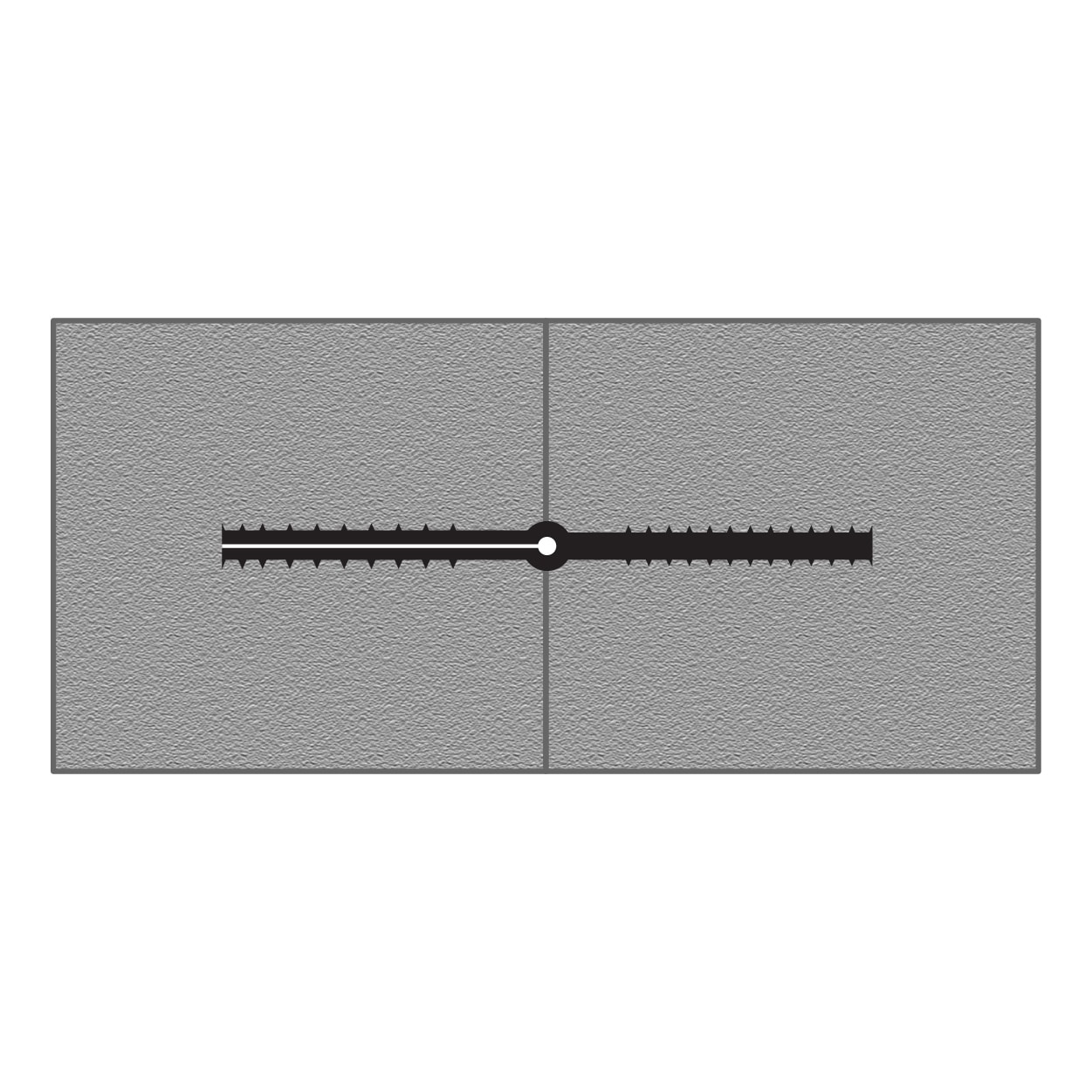
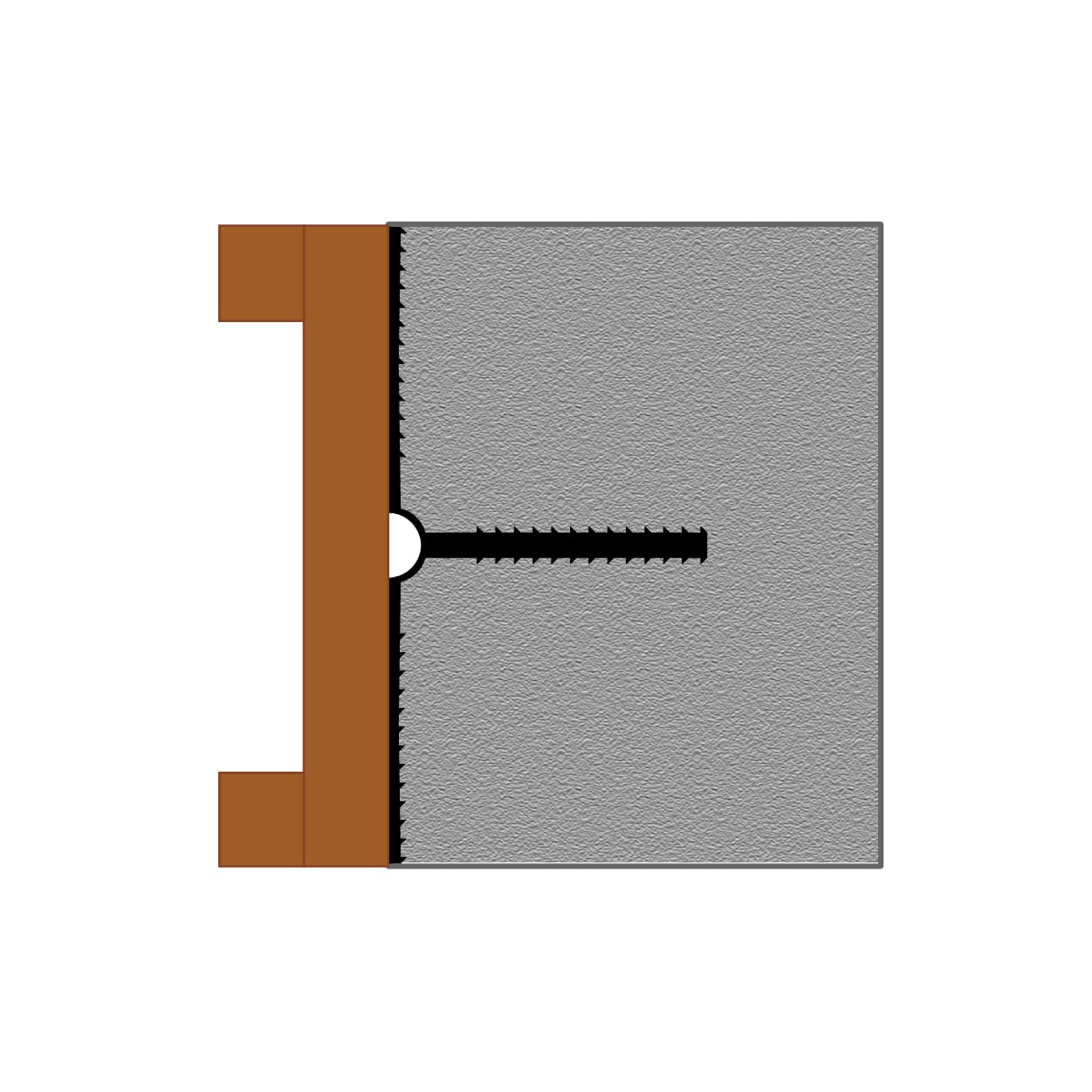
Split flange waterstops are specified when simplified forming is a priority. The flange is split lengthwise so it can be opened, laid over the bulkhead, and attached during placement of the first concrete element. After the bulkhead is stripped, the flange is closed and anchored for placement of the adjoining concrete. This approach eliminates the split formwork normally required for embedded waterstops, making split flange profiles particularly attractive when forming complexity or schedule pressure favors a simpler sequence. The hollow centerbulb sits over the joint and accommodates lateral, transverse, and shear movement, forming a continuous diaphragm intended to prevent the passage of liquid through the joint.
Split flange profiles have an important limitation: they are suitable for straight runs only. Transitions and intersections are not practical with these profiles, which means projects with frequent changes of direction or complex joint geometry will typically need a different waterstop family. Split flange waterstops are produced in widths of 6 inches and 9 inches across two weight classes and head pressure ratings, with the appropriate size depending on the project’s expected joint movement, hydrostatic head pressure, and concrete thickness.
Typical Applications
✓Commonly Specified For
- Straight-run joints with no transitions or intersections
- Projects where simplified forming is a priority
- Expansion, contraction, and isolation joints in straight runs
- Joints subject to lateral, transverse, or shear movement
- Water and wastewater treatment plants
- Reservoirs, tunnels, and containment structures
- Potable water contact applications
- Long runs of slab or wall joints without changes of direction
→Other Profiles May Be Considered When
- The joint layout requires transitions, intersections, or changes of direction — see Ribbed Centerbulb
- Better sealing characteristics are desired — see Ribbed Centerbulb
- The joint has continuous reinforcement and minimal movement — see Flat Ribbed
- The application is a slab-on-grade joint — see Base Seal
- Larger joint movements are expected — see Tear Web profiles
Profile selection should always be verified against project specifications and engineering requirements. Contact us if you’d like assistance reviewing options for your application.
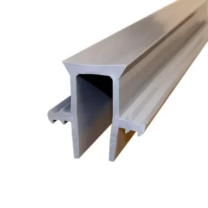
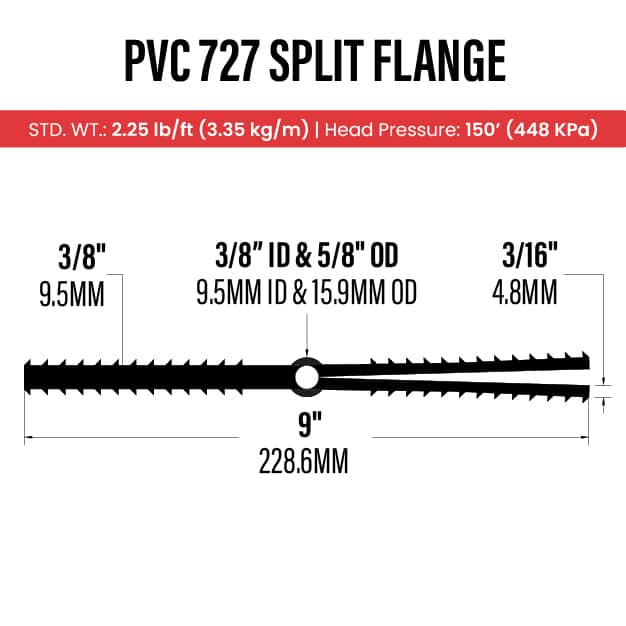
Available Sizes: Profile 724 and Profile 727
Sika Greenstreak produces split flange waterstop in two profile sizes to suit different joint widths, movement requirements, and head pressure ratings.
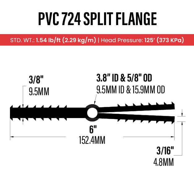
Sizing considerations generally include expected joint movement, hydrostatic head, and concrete cover. Contact us if you’d like help cross-referencing a profile against your spec.
Split Flange Waterstop Installation Overview
Split flange waterstops install with a different sequence than other embedded profiles. The flange is split lengthwise so it can open up around the bulkhead — eliminating the need for the split formwork required by symmetrical embedded profiles. Heat welding is generally the recognized method for splicing PVC waterstop, though split flange profiles are limited to straight runs and don’t typically require field fabrications for changes of direction. Always refer to the manufacturer’s installation guide and project specifications for complete instructions.
Open & Attach
Open the split flange and attach it to the bulkhead for placement of the first concrete element.
Pour First
Place and consolidate the first concrete element, encapsulating one side of the waterstop.
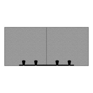
Strip & Close
Strip the bulkhead, close the split flange, and anchor it in position for the adjoining pour.
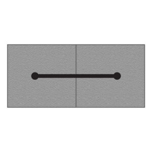
Pour Second
Place the adjoining concrete element to encapsulate the second flange and complete the diaphragm.